|
|
|
|
|
|
|
||||||||||||||
|
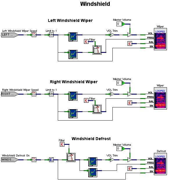
Windshield V+ Design
The Windshield V+ design (Figure 33) contains three models:
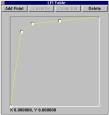
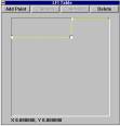
The wiper models are similar and differ only by their inputs and which channel of the front speakers the sound plays on (Left Windshield Wiper plays on the left channel, Right Windshield Wiper plays on the right). The volume for the wiper sound is a function of the wiper speed input. The input passes through an LFI shown in Figure 29. The curve shows that it increases in volume rapidly and levels off to 1. The frequency for the wiper sound is also a function of wiper speed. It passes through the LFI shown in Figure 30. This is what is called a step-function. On the Beech 1900D, there are two wiper speeds: slow and fast. When our host computer sends over the wiper speed, it uses 50% for slow speed and 100% for fast. Note that the step occurs at about 60%, which provides a little cushion past the slow speed mark. The output of the frequency LFI is sent through a 1st Order Low Pass Filter, which ramps the speed change to simulate the mechanical limitations of the wiper system (wipers don’t instantly change speed).
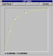
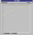
The Windshield Defrost model is relatively simple. It accepts an input form the host called Windshield Defrost On, which is a simple toggle. The input is sent through a Float to BOOL object, and passed along to a low pass filter, which is used to smooth any abrupt changes coming from the host. The output of the low pass filter is then split into the volume and frequency paths for the player. The player plays the sound on the front speakers. The enable pin of the player is hooked directly to the Float to BOOL The balance pin is a constant allocated to both channels. The volume is a function of the Defrost On input. It uses an LFI shown in Figure 31. The curve for this LFI starts at 0, then rises at a good rate and levels off at 1. The frequency is also a function of the Defrost On input. It uses the LFI shown in Figure 32. This curve starts at about 55% and gradually rises to 100%. The Windshield Defrost model is actually designed to be more sophisticated than is needed by our simulator. In the Beech 1900D, the windshield defrost is either on or off. If the input was a variable range to simulate multiple defrost fan speeds, we could make some simple changes to the model to accommodate a range. All we would have to do is move the Float to BOOL to be used only by the enable pin. This would then actually make complete use of the LFIs for volume and frequency.
Figure 33. Windshield Design |
|
|
|||||||||||||
|
|
|||
| Home | About | Products | Support | News | Find | Contact Us | |||
|
©SimPhonics Legal Notices Privacy Policy |
|||