|
|
|
|
|
|
|
|||||||||||||||||
|
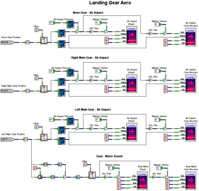
Gear Aero V+ Designs There are four models in the Gear Aero V+ worksheet:
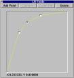
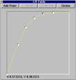
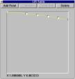
The first three deal with the air impact on the nose, left main, and right main landing gear. For the most part, these models are the same. They differ in that they each have their own specific input for gear position. They each have two players for the air impact sound, one for the rear speakers and one for the sub-woofer. Each of the players has the balance and enable inputs set to 0 and 1 respectively. The volume for the players is a function of air impact pressure and gear position. Figure 16 contains the LFI for air impact’s effect on volume for all three models. The curve starts at 0, rapidly rises and levels off at 1. The gear position input passes through a 1st Order Low Pass Filter whose output is split between the volume path and the frequency path. Along the volume path, it goes through the LFI shown in Figure 17. This curve also starts at 0 and rapidly rises and levels out at 1. This makes sense. As more of a landing gear strut is exposed to the air, the volume of air rushing past it increases, and as the speed of the strut flying through the air increases, the volume of air rushing past it also increases. The frequency for the air impact player is a function of gear position only. As more of the gear strut is exposed, it lowers the frequency of the air impact noise (similar to the flaps frequency), as is shown in Figure 18.
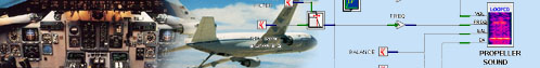
The Gear – Motor Sound V+ worksheet is shown at the bottom of Figure 19. In the Beech 1900D, all of the gear extend and retract at the same rate. Since this motor sound is barely heard in the cockpit, we felt that it only needed to be attached to one of the gear struts. There are two players for this model: one for the rear speakers and one for the sub-woofer. The frequency, balance, and enable inputs are constantly 1, 0, and 1 respectively. The gear position input passes through a High Pass Filter object, which is then multiplied by the gear position input to produce an output as long as the gear position is changing. A Low Pass Filter is then used to smooth out any abrupt changes in gear position coming from the host computer. The output of the low pass filter is then provided as volume input to the gear motor sound player.
Figure 19. GearAero Design |
|
|
||||||||||||||||
|
|
|||
| Home | About | Products | Support | News | Find | Contact Us | |||
|
©SimPhonics Legal Notices Privacy Policy |
|||