|
|
|
|
|
|
|
|||||||||||||||||||
|
Engine Design
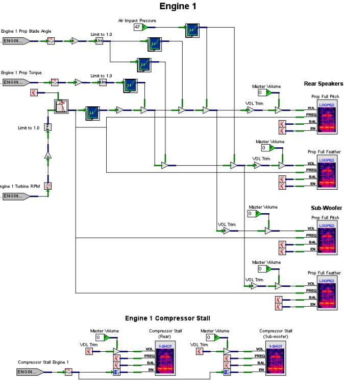
There are two engine worksheets that are used to simulate the two engines for the Beech 1900D. Figure 9 sheet for Engine1. The worksheet for Engine2 differs only in the input ports and channel allocations for the Looped FXDirect Player with Bal, Vol and Freq objects. The inputs to Engine1 are as follows.
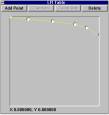
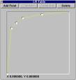
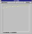
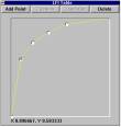
On a turbo-prop engine such as the Pratt & Whitney PT6A-67D, the sound that is heard comes primarily from the noise of the propellers slicing through the air. In the Engine1 design, two WAVE files are played. The first is a looped sample of the engine at full pitch. The second is a looped sample of the engine at full feather. Four Looped DirectFX Players are used. The first pair, labeled Rear Speakers, plays on the rear speakers with the balance mostly skewed to the left (Engine2’s rear speaker players are skewed mostly to the right). The second pair plays on the sub-woofer to add low frequency rumble. There are four inputs to a Looped FXDirect Player with Bal, Vol and Freq object: Volume, Frequency, Balance, and Enable. The Balance is fixed as per the skew discussed earlier. The Enable is always activated. The Volume and Frequency inputs are variable based on the discussion that follows. The Volume input for the full pitch sound is a function of Air Impact Pressure, Propeller Blade Angle, Propeller Torque, and Turbine RPM. Each of these inputs runs through a Float LFI object. Each of these LFIs becomes a multiplier to determine the final volume provided as input to the player. The LFI for Air Impact Pressure, shown in Figure 4 , is a curve that has little effect, but slowly decreases the output as air impact increases. The Propeller Blade Angle LFI, Figure 5 , is a curve that rapidly increases and levels out as blade angle is increased. Figure 6 contains the Propeller Torque LFI, which is a curve that has little effect, but slowly increases as torque increases. The LFI for Turbine RPM, Figure 7 , is a curve that creates a good amount of gain as RPM increases.
The Volume input for the full feather sound is also function of Air Impact Pressure, Propeller Blade Angle, Propeller Torque, and Turbine RPM. The only difference between this “equation” and the one for the full pitch sound is that the LFI for Propeller Blade Angle is inverted, as shown in Figure 8. In other words, as blade angle increases, the output value decreases. Compare this curve with the one in Figure 5. The Frequency for both the full pitch and full feather sounds is directly affected by the Turbine RPM input. As the RPM percentage is increased, so is the frequency. A First Order Low Pass Filter is used to smooth the change in frequency, which gets rid of any abrupt changes that might come from the Host Computer. At the bottom of the Engine1 worksheet is a model called Engine 1 Compressor Stall. This is a pretty simple model that simulates a turbine compressor stall, much like a backfire on your car. It has two one-shot players: one for the rear speakers, and one for the sub-woofer (a One-Shot FXDirect Player only plays through the sound once). The volume, frequency, and balance pins for these players are fixed constants. The enable pins are hooked to the Compressor Stall Engine 1 input port, which is commonly implemented at the host computer as a malfunction. Note that the Master Volume worksheet connector goes to a Multiply Float object, which has final control of the volume for all the players in this worksheet. This will be the case in subsequent design discussions, and consequently, not mentioned again. Also note that a Multiply By Static Data Constant object labeled VOL Trim precedes the Master Volume multiplier. This allows for fine-tuning of the volume setting for a given player. All players in subsequent designs have a VOL Trim “pot”, so again, no need to mention them anymore.
Figure 9. Engine1 V+ Design |
|
|
||||||||||||||||||
|
|
|||
| Home | About | Products | Support | News | Find | Contact Us | |||
|
©SimPhonics Legal Notices Privacy Policy |
|||